.
Probe Selection
.
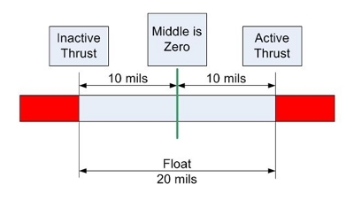
The selection of probe measurement range is based on the bearing float or clearance added to the anticipated or tolerated white metal removal. This will typically be in the region of 15 – 20 mils, and therefore the measurement might be +/- 10 mils from a central position. However, depending on the operational mode of the unit, the measurement might be referenced to a zero position; for example, from the active face of the bearing, the acceptable movement might be -5 to +15 depending on which way the measurement is made.
Probe Location
.
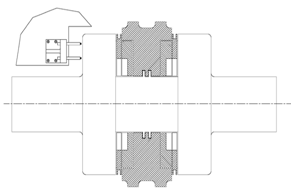
It is desirable to have the probes located as close as possible to the thrust bearing, even directly observing the thrust collar. This helps to minimize errors which might be caused due to the thermal expansion of the shaft. Clearly, this is not always possible, and therefore care must be exercised when positioning and mounting the thrust probes. The most common recommendation is keep this distance to no more than two (2) shaft diameters from the thrust bearing. If this distance becomes much greater, the monitoring system should be configured to take account of the anticipated thermal expansion of the section of shaft between the thrust bearing and the mounting position, particularly if the thrust is being used as a trip initiator.
Probe Installation
.
As with almost all probe installations, special brackets or housings may be required to achieve correct probe positioning and gap adjustment, and these will invariably need to be designed and customized to suit the prevailing mechanical space available inside the machine cover.
Monitoring System Configuration
.
Following mechanical installation, the probes must be appropriately gapped with the rotor at rest in a known position, taking care to ensure that the total expected movement in the direction of movement does not exceed the linear range of the installed probes. This is often done by jacking or ‘bumping’ the shaft against the active thrust shoe or to another known position. The probes can then be gapped and the DC voltage noted and entered as an offset in the monitoring system to achieve the desired ‘zero’ position.
As previously discussed, the allowable shaft wear, the final shimmed thrust bearing float, the probe linear range and the alarm set-points should all be factored into the calculations for determining the final gap. This attention to detail will ensure that when operational, the shaft position remains within the best linear region of the probe, and that any alarm set-point also remain inside the measurement range of the probe.