.
Differential Expansion
The rotor of a machine is physically held in place by the thrust bearing, but depending on where the fixed or pin point is located on the machine, the thrust bearing can also slide as the machine expands. In any case, as the machine heats up or cools down, it is vital that the rotor and the casing ‘grow’ at the same rate so as to avoid rotor-to-stator contact which will invariably destroy the machine. Therefore, during transient phases of operation (start-up or cool-down) heat soaking and dwells are used to ensure that thermal expansion or contraction to not cause rotor-to-stator contact.
It is common to use non-contact probes (eddy current probes) attached to the turbine casing to observe the rotor, thereby measuring the difference between the movement of the rotor and the casing as they thermally expand.
Eddy current probes are available with measurement ranges up to 1/2 inch or more, and so sometimes this measurement can be made conventionally, i.e. with the probe directly observing a rotating flange or collar. However, in some instances, the range required is greater than the probe range available – due to physical or target area limitations, and therefore an alternative method must be implemented to measure the differential expansion.
Conventional Monitor
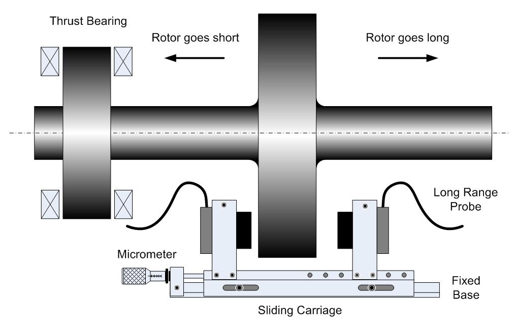
In a conventional probe arrangement, a single long range probe is mounted parallel to the main axis of the shaft and observes a target which is perpendicular to the shaft. The change in the axial position relative to the casing is then indicated directly by the DC component of the signal, or the ‘gap voltage’.
In keeping with eddy probe requirements, this method requires target area at least 1½ times larger than the probe tip diameter which is not always possible, since the long range probe can be up to 2 inch in diameter.
Complimentary Monitor
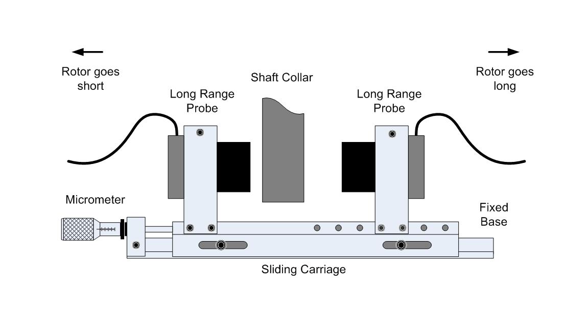
In the Complimentary method, two probes are used to measure the expansion for a smaller target area, and the linear ranges of the two probes are then added together to make the total range required.
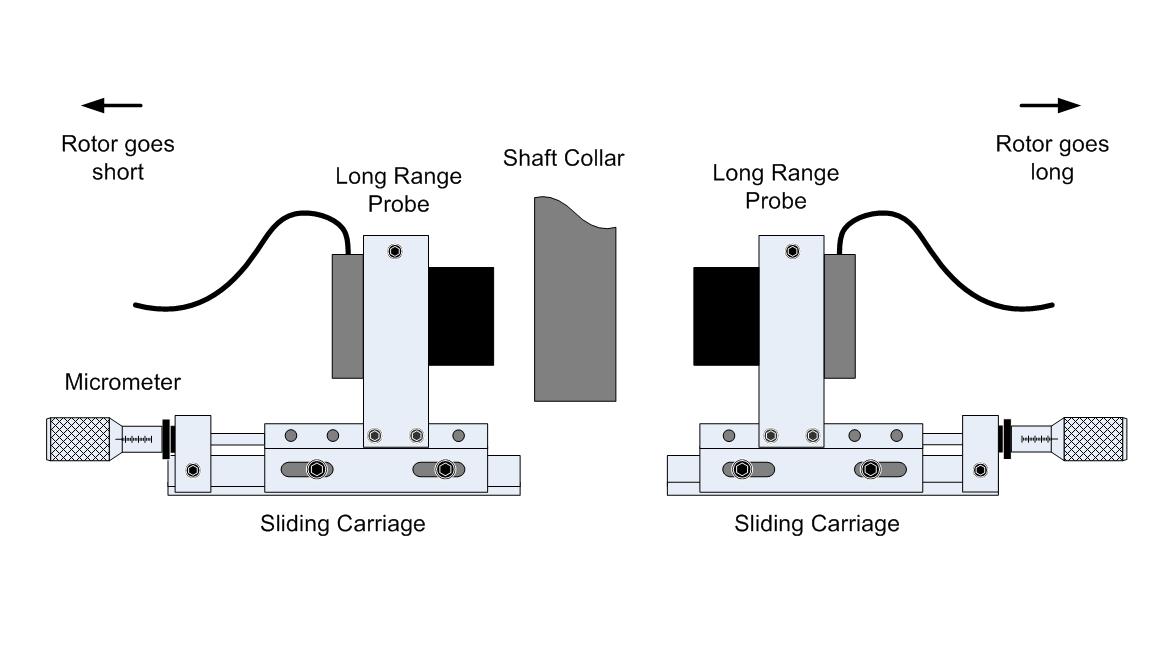
There are a number of variants on this theme, but the probes are usually mounted facing each other, one on each side of the target, so that the moving target area will always be within the linear range of one of the probes. This arrangement allows the use of smaller probes while still achieving the desired linear range.
The probe mounting arrangement can be problematic depending on other equipment which may be located in the area around the collar being used to measure the Differential Expansion. Ideally, the two probes will be mounted onto the same dual probe carriage as shown above, but other arrangements can be accommodated in the system configuration, but are more complex to set-up.
Ramp Monitor
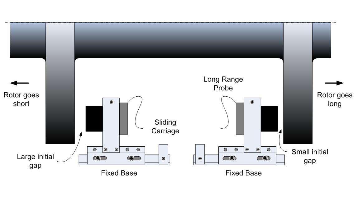
In ramp mode, two probes are used to observe a ‘butterfly’ surface machined onto the shaft. This can be concave or convex – the amplification affect is the same.
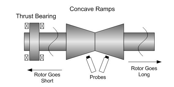
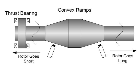
In this method, the small diameter probes can be used to measure the small radial change between the probe tip and the target, and the resulting axial change corresponds to the increased range provided by the mechanical advantage of the ramp. The increased range is proportional to the sine of the angle of the ramp. For example, two angles are commonly used – 11° and 14°. The sine of 11° is approx. 0.191, which provides a mechanical multiplier of 1.0 / 0.191 = 5.24, and for 14° the resulting multiplier is 4.13. Using an 11° ramp, a standard 100 mils probe will now provide a range of 5.24 x 100 = 524 mils.
As illustrated above, two probes are installed but only one actually performs the measurement. The second probe is used for correction of any small radial movement due to bearing clearance for example, which might otherwise cause a large apparent axial movement which would result in a large error in the measurement.
There is a sub-method sometimes used for ramp differential expansion, where only a single ramp is available. The same method applies, and in this case, the non-ramp probe is used for the radial correction.