.
Radial Vibration Monitoring
Radial Vibration Monitoring is the backbone of the entire machinery condition monitoring ethos; it provides invaluable information as to the condition of the machine, and is used in virtually every machinery monitoring installation.
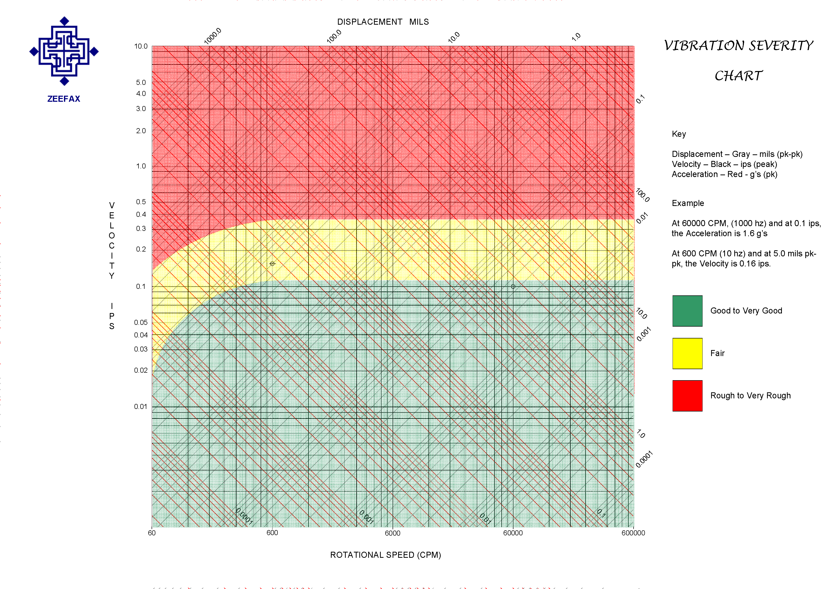
Vibration is simply a measurement of the components of oscillatory motion, and is expressed in terms of peak-to-peak displacement, peak velocity or peak acceleration.
Displacement
The displacement is the physical distance which a component moves from rest. Usually measured in mills peak-to-peak, which is the total excursion of the component from one extreme position to the other, around its resting point or average position. Displacement measurements are used for determining the radial or axial clearances – for example, thrust or shaft movement – or the relative vibratory motion between the rotating and the stationary parts of a machine.
Velocity
Velocity is the rate at which the displacement changes, and is normally associated with structural vibration of bearing caps or machine casing. It is used to determine the severity of the oscillatory motion and is the basis for many established operating envelopes, yet provides only limited protection for the internal clearances of a machine, due to the fact that machine case or bearing cap vibration is the complex response of the structure to the various forcing functions which exist whilst a machine in in operation.
Velocity is however a useful parameter to describe vibration severity, since it is directly proportional to time, and represents work done or energy dissipated at a point over a wide frequency range.
Acceleration
Acceleration is the rate at which the velocity of the component changes, and since it is proportional to the square of the frequency, acceleration levels are strong at higher frequencies, even for very small displacements. Therefore, acceleration measurements are useful for high frequency machinery parameters – such as blade passing, gear meshing or rolling element bearing frequencies.
Acceleration is important because it is directly proportional to the force which is being applied, and is therefore a good indication of the potential of the vibration to do damage to the component.
Measurement Techniques
Bearing Cap or Structural Vibration
Positioning a sensor atop a bearing cap or onto a structure measures the response or motion of the component relative to space, and is the least informative method for machinery protection applications. This is simply a measure of the response of the structure to the excitation input force and is affected by the mechanical impedance of the structure which will change as the operating conditions change. It should therefore not be used in isolation for machinery protection, but it can be used in conjunction with other data for machinery diagnostics.
Seismic sensors – either velocity sensors (velometers) or accelerometers – are used, usually attached using a short threaded stud onto a spot face, machined onto the component specifically for the purpose. It is vitally important to ensure that the mating surface between the machine and the sensor is smooth, flat and clean, and that the sensor is appropriately tightened onto the stud; this ensures good vibration transmission through to the sensing element which is housed inside the sensor case.
Shaft Relative Vibration
Non contacting eddy current probes are typically used to measure both the radial vibration and the axial motion of the shaft, due to the fact that they have a very wide frequency response – from DC (used to measure the gap) up to 10 kHz or more, making them ideal for measuring shaft radial vibration also.
Usually, eddy probes are installed using special holders or housings, designed to protect the probes and wiring and to maintain the relative position (gap) once set. The probe holders are then attached to the bearing case, thereby making the measurement correspond to the relative motion of the shaft within that bearing.
This type of measurement is much more indicative of the condition of the bearing by revealing the motion of the shaft within the bearing, and thereby indicating the extent of any wear which may be occuring.
Absolute Shaft Vibration
The two previous techniques may be combined to provide a measurement of the Absolute Shaft Motion or vibration within free space.
This parameter is important for large steam turbines, since (generally) the bearing pedestals are separate from the turbine case and since the internal radial clearances are very close – of the order of 30 – 50 mils – within the turbine, a measure of the Absolute Motion of the shaft in free space is vital for the protection of the turbine during operation.
An absolute shaft measurement is recommended if the bearing housing is considered to be ‘flexible’ i.e. if the case vibration is greater than about 20 % of the absolute shaft vibration.
Historically, the absolute shaft motion is measured using a shaft rider, which penetrates the beaing cap and rides on the rotating surface of the shaft. Mounting a seismic sensor onto the free end of the shaft rider then converts the oscillatory motion of the shaft rider into an electrical signal for use in any monitoring equipment. The resulting output of the seismic sensor is the corrected absolute shaft vibration.
Shaft riders have a relatively poor frequency response – usually limited to only 2x running speed – and since often only a single device is installed, the diagnostic capabilities are also restricted. The more modern approach is to replace the shaft rider with a combination of relative and seismic sensors to make this measurement; the integrated vibration (displacement) of the structural component (bearing cap) is vectorially combined with the relative shaft vibration (displacement) measured directly. This yields the resultant free space vibratory motion of the rotating shaft. Furthermore, by installing two sets of probes – typically separated by 90 degrees in the same plane – a true representation of the absolute vibratory shaft motion within free space can be examined together with a determinantion of the average shaft centerline position and path (locus) during transient conditions.
Sensor Selection
Accelerometer
Benefits
- Wide frequency response – typically 1 hz up to 5 khz
- No moving parts – excellent reliability
- Easy to install
- Unaffected by external electromagnetic fields
- Operates below resonance – excellent amplitude and phase response at all frequencies
Considerations
- Sensitive to mounting conditions – temperature, mounting surface quality and condition
- Require external power source for internal electronics
- Require single integration to obtain strong signals at low speeds
Velocity Sensor
Moving Coil / Moving Magnet
Benefits
- Easy to install.
- Self generating with relatively strong output throughout the usable range.
Considerations
- The output voltage is linear only above sensor resonance, with both amplitude and phase errors below the resonant frequency.
- Frequency range limited to about 1500 Hz.
- Has moving parts which can wear with time causing unpredictable changes in sensitivity.
- Regular calibration and checking is recommended.
- The generated output voltage is based on the inductance between the moving magnet and the stationary coil.
- Therefore, they are affected by external electromagnetic interference when positioned near to electrical equipment.
- Tend to be rather large, and therefore accordingly heavy.
- Generally sensitive to the installation angle. Should be mounted vertically unless otherwise specified.
Piezoelectric Velocity Transducer
A piezoelectric velocity sensor is basically a seismic piezoelectric accelerometer which includes an internal electronics module. This module integrates the resulting acceleration signal, and the output is the corresponding velocity signal.
This method can increase the frequency response of the velocity signal all the way up to 5kHz or more, making this device much more usable for machinery monitoring applications.
The use of internal integration avoids the associated low frequency noise problems of remote signal integration, and since it has no moving parts, these small devices tend to be more reliable and robust than moving coil sensors.
Eddy Current Probe
Benefits
- Wide frequency response – typically 1 hz up to 10 khz
- No moving parts – excellent reliability
- Easy to install
- Mainly unaffected by external electromagnetic fields
- Operates below resonance – therefore has very good amplitude and phase response at all usual machinery frequencies.
Considerations
- Sensitive to mounting conditions – temperature, target surface quality, cleanness and flatness
- Require external power source for proximeter / driver electronics