Casing Expansion
In large turbo machinery, the thrust bearing assembly is usually located either inside the front standard or between the HP/IP turbine and the first of the LP turbines and it is intended to control the axial movement of the rotating shaft relative to the stationary case, as it warms up during start-up periods. In this arrangement, the front standard is usually permitted to move axially to accommodate the thermal expansion in the other direction from the HP/IP turbine sections, but it is restrained from moving radially.
The drawing below shows a large turbo-alternator machine. Starting from the right, notice that the thrust bearing is located between the HP and LP1 turbines, and that case expansion is measured in two places – either side of the thrust bearing, at the HP turbine case, and then at the LP1 turbine case. It is also worth noting that since the thrust measurement is so critical, it is typically provided with dual probe redundancy.
![]()
Depending on the physical layout of the machine and the location of any critical areas, sensors may be installed between the front standard and the foundation, or between the front standard and the HP/IP casing. For Case Expansion, these are usually Linear Variable Differential Transformers (LVDT) which provide greater linear range than an eddy probe, and can accommodate the expected greater expansion values at these locations. The LVDTs are usually configured with a spring loaded plunger and are installed with the plunger ball-bearing tip riding against the moving case, ideally on a machined flat surface which is perpendicular to the main axis of the rotor.
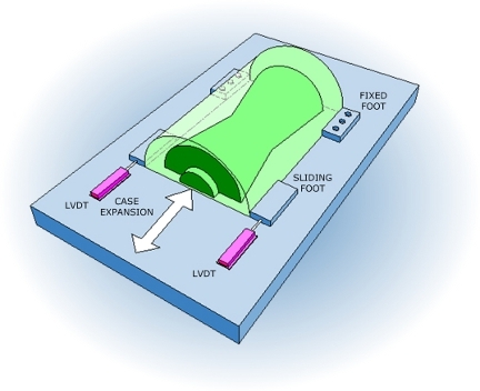
As a precaution, dual LVDT sensors may be fitted, one on either side of the case, and examination and comparison of the output from these sensors can reveal another source of operational trauma in large turbines, known as ‘crabbing‘. Large and heavy mechanical items within the machine train are designed to expand away from the fixed or pinned point as they heat up, and they will rest on engineered slide surfaces which should be kept clear, clean and free from debris, and should also be kept well lubricated. As the machine train warms up or cools down, these slides can stick causing the case to want to rotate towards the sticky side, hence the term ‘crabbing‘.
In some installations, the case expansion is also monitored at intermediate positions all along the machine train, all the way along and up to in-between the last LP turbine and the Generaator. LVDTs can be used, or alternative methods using mechanical cantilevers are sometimes used, which use cantilevered targets to extend the measurement range of standard eddy current probes to meet the extended range required.